Wednesday, October 10, 2012

Pulling troubles

So after I had the easy parts off the lathe my first hard part to tackle was the parts that are attached to the outboard side of the headstock spindle. If you look at this exploded diagram you can see the parts in order of placement starting with the hub, plate, retainer (I'll get back to this little bastard in a second) spindle pulley assembly, bearing, gear hub assembly, etc etc etc. My first attempt was to put my biggest 3 jaw puller on the spindle and grab onto the spindle pulley hub, because it had the biggest area to grab on to. I figured if I could break this loose, it would push on the plate and hub and pull everything off in one fell swoop. I did not at this time figure out that the retaining ring (circled in red) was holding the the spindle pulley assembly from moving.

Needless to say, that wasn't going to work. You might be surprised at how long it took me to figure that one out. Eventually I came up with what you see in this picture. It's using one of my smaller pullers on the hub, but I had to first created a small flat bar puller center, to cover the hole of the spindle so that my puller had something to push against. Then because the jaws were barely contacting the hub I wrapped some bailing wire through the un-used pivot holes on the jaws. This was just enough for me to finally pull that hub off.

Finally I got the snap ring off with a typical pair of snap ring pliers. This was another tool I inherited from my Grandfather. I had never known how to get snap rings off before I discovered this tool. Seems kind of stupid but it was quite an Aha moment.

The rest came off relatively easy with my handy puller plate center coupled with my bigger 3 jaw pullers.


This was a big triumph that actually took me several days of futzing around and trying different things to continue disassembly. I'm trying to keep up my pace on this lathe and not get discouraged or bored with it. I'm realizing how long this trip is going to be and wonder how much trouble I'll have keeping focused.


Sunday, September 23, 2012

Parts Painting

Here are some of the first parts that I had gotten cleaned up and ready for refinishing. For the smaller parts I find it easiest to just paint these with a small artists brush by hand. There are so many nooks and crannys and places that need to be masked on some of them that its just easier this way. I'm going to be spraying the larger pieces outside.

Among the parts included here are the leveling feet plates, door hinges, compound and tool rest, and the main apron casting.


There is still a lot more cleaning and tearing down going on, but I find it helps keep my motivation going if I can move onto refinishing some pieces already. It makes me feel like I'm making progress.

3 Jaw Chuck

My first attempt at buying a chuck didn't work out too well. I forgot to make sure it was a plain back and it ended up having integral threads. So I had to return it. My second attempt worked out well.

For a pretty good price I picked up a nice Burnerd 5" 3 jaw universal chuck on eBay. It's a plain back, and it had a 1 1/2" x 8 adapter plate already on it.  I took it all apart and cleaned out the old chips and grease and lubed it all up with way oil.

Besides some wear on the ring and a few chipped gear teeth on the pinions it is in good shape. Luckily the chipped teeth don't affect the function as far as I can tell. 

Since the 1-1/2" x 8 backing plate is smaller than the 1-3/4" x 8 that the Clausing has I believe I might be able to re-bore, and re-thread the plate. That way I don't have to buy another backing plate. 

I did buy a brand new backing plate with the correct nose thread from AMTOOLS but I think I'm going to use that on a new 4 jaw chuck when I get one. 

Side Bench

This was a quick side project. The back wall of my shed has an angled portion where the alley wraps around  the back. The lathe fits right up against the angled portion of the wall. I wanted to fill in the small triangular area with a work bench that is roughly the same height as the lathe chip tray.

It's a very simple build. A few 2x4's and a piece of plywood all screwed together. It's screwed to the studs of the shed with timberlock screws. I then mounted my big Crafstman vise to the table. It's not the most accessible bench, but it makes use of an otherwise wasted space. The vise was my grandfather's and every time I get to use one of his tools it puts a smile on my face.

Monday, September 10, 2012

Compound Issues


The compound and the tool post slide both had some issues I had to deal with. The first thing that came up on dis-assembly of these parts was that the end of the compound slide was pretty well chewed up.  I can only assume that someone had the tool post slide back far enough to expose this area and had run it into the chuck. For some reason someone had drilled a hole into this area and inserted a pin. The end effect was to keep the tool post slide from extending over this chewed up area. Why? I have no idea. The problem was that with this pin installed, I could not remove the tool post slide. I chose to cut the pin off with an abrasive disc in my angle grinder. This way at least the rest of the pin was filling in the hole at the chewy end. I tried to cut it off with a bit left over to file down but I ended up not being as clean as I wanted. I need more patience.  However I was finally able to remove the tool post slide.


One of the first things I noticed even on the pictures on eBay was that the tool post slide was evidently brazed back together at some point. With my limited machining knowledge I can only come up with one scenario in which it would be possible to break the slide at this location. I think someone over-tightened the tool post which put too much pressure at the T slot and the cast iron snapped. It was brazed together, however none of the excess was ever machined off. I decided to grind off the majority of the excess with my angle grinder. Then I went to my stationary belt sander to dress the rest, going slowly and checking for square the entire way. It may not be as precise as it should have been but I don't have a mill yet.

How will these issues affect the overall accuracy of the lathe when I get it running? I have no idea. I could imagine the chewy edge of the compound not supporting the tool slide as well as possible, which could result in some flex.

I'm not sure how a slightly out of square tool slide might affect things either. I'd imagine maybe some special set ups that use the sides for reference might suffer. Until I start learning how to use the machine I probably won't know. Can I fix these things later? Probably. But for now it's on to the next mess...

Tuesday, August 14, 2012

Filth!

This lathe is utterly filthy. Every square inch of it is covered in grease, grime and metal chips. While unloading in the pouring rain, the thick coating of gunk was actually helpful, it kept the surface rust from forming. Now that it is in place and I'm tearing it down, it isn't as welcome.

After the initial start up, and being able to finally poke and prod around the inside of the lathe I've decided to go ahead and commence a complete tear down of the machine. There is just no way of cleaning it in place. At some point in it's life the lathe got a cursory paint job. So I've also decided to completely strip it off and re-paint it. I know this is mostly cosmetic and does nothing for the function of the lathe but I think it will be worth it.

My strategy for tear down is mostly this; removing parts, doing a primary cleaning/de-greasing in the parts washer, stripping painted parts, then wire brushing all surfaces that are not sensitive to a wire brushing. By that I mean I don't want to be taking a powered wire wheel to any precision surfaces.

The exploded diagrams that are part of the manual have probably instilled a little too much confidence in me. I am probably not being as systematic as I should be about the tagging and bagging of all the individual parts. So far after the primary cleaning I've been placing parts into boxes that are designated for the sub-assemblies according to the parts diagrams. So the tail stock gets its own box. The headstock, the compound, etc. I figure the smaller components will be easy to figure out when going back together because I know at least which sub-assembly they go to. We shall see how this works out.

I'm not sure the posts from the tear down will be terribly exciting. It's mostly a lot of cleaning.

I didn't get my parts washer until about a week after I started. What a great little device. I was going to buy the Harbor Freight small parts washer, but it was plastic, and someone suggested I try and find a metal version. I simply don't have the space for the larger steel model from Harbor Freight. Hell I don't have the space for the small version. I'd highly recommend the model I found, despite other reviews that say the pump bracket gets damaged in shipping. Mine survived shipping. It's simple, small, does what its supposed to do. I filled it with 3.5 gallons of paint thinner and got to cleaning...

I'm uploading more pictures than this blog is showing on my web album, for those of you who care to see more.


Monday, July 30, 2012

It's Alive!

Sunday was beautiful compared to the rain filled misery of moving day. The first task of the day was to re-install my fence. Surprisingly I think it's leaning less than when we took it apart. I'm pretty sure a stiff breeze could have brought it toppling over.

I started looking over the lathe and getting familiar with all the levers, dials, screws, etc. I had seen it run before but I didn't have the knowledge or the time to test out every little thing. So my first order of business was to get the motor running so I could test everything out.

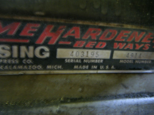
A little background first. The motor on the 4914 is a 1 horsepower, three phase, 220 volt model. Three phase is the type of current that industrial sites receive, not your typical DC residential apartment which has single phase power. There are several ways you can drive a three phase motor on single phase power but I will only be discussing the path I chose, using a Variable Frequency Drive, or VFD for short.

After doing a lot of online research on various brands and types, I purchased a Teco Westinghouse FM50-101-C. It is probably the cheapest most robust VFD I could find that met the requirements I need. Essentially it takes 110V single phase power, and converts it into 220v three phase, and it's rated for 1 HP. That's important, you have to make sure the VFD is rated for your motors HP. It seems that in the early days of VFD's you had to choose a VFD that was rated for MORE than your motors HP but I've found that is not the case anymore. Also, I've found a lot of other home machinists have used this same model to hook up their three phase machines, so there is a lot of 3rd party advice on how to connect one.

I'll be getting into the really cool functions of the VFD and exactly how to hook one up in a later post. For now, I just wanted to get the motor running. Call me ghetto if you like, but I live in an apartment, and my shed doesn't have power, so I run any electrical devices off a heavy duty 12ga extension cord. Crazy you say? Well maybe. My friend Grant who helped me unload it told me I should hire an electrician! ha!

The lathe has a heavy duty three phase fused disconnect switch on the rear of the machine. I opened this up and started disconnecting both the motor leads and all the wires coming out of the drum switch, which is used to put the machine into forward or reverse. All I needed was the 3 leads from the motor plus it's grounding wire. I hooked these up to the VFD and plugged it in. I made sure the lathe was in direct drive (not in back gears) and that the feed control lever for the lead screw was in neutral. I hit the start button and the motor purrs to life. It's alive!


The motor's "native" frequency is 60hz, so by lowering that frequency the motor runs slower. I slowly ramped the speed up to 60hz and everything sounded good. No crunching noises, relatively quiet. The belt drive was set somewhere in the middle of it's speed range. I ramped down to half speed, 30hz, and stopped the motor. I wanted to try out the feed control and since the tumbler bracket for the quick change gear box is broken I wanted to keep it in relatively low speed for testing. I set the QCGB to a relatively fine feed rate and had to wedge a wrench under the broken bracket to keep it in gear. I started up the motor again. The lead screw was slowly turning! All the levers on the apron were pretty tight, but I was able to engage the half nut lever and see the carriage move on it's own. I then tried the longitudinal feed lever and again, the power feed worked. Finally I tried the cross feed and that too worked! So far so good.

The feed control was set in the lower position so it was feeding away from the headstock. I stopped the motor and put it into the upper position to test feeding towards the headstock. This is when I got some nasty grinding noise and immediately stopped the motor. What I found was that when the feed control lever is in it's upper notch, it's not quite engaging the gear train. I pulled it out and pushed it PAST the notch and re-tried. No grinding, everything works. I'm hoping something may just be misaligned and can be fixed. Overall not a huge problem.

At this point I moved the belt over to the highest speed position of 1700 RPMs and let her rip up to 60hz. Whoa, no bad noises but this thing can scream at these high speeds.  I'm hoping the restoration will quiet a few things down a bit.

I had not attempted back gears because I couldn't seem to get the back gear pin to pull out. I was spraying it liberally with PB blaster when finally I gently pried it loos with a screwdriver. Then I was able to engage the back gears and try it out at low speed. As before everything functioned properly.

Now that I know everything works for the most part, I decided to start tearing into the machine to clean it up... But that's for another post.


Tuesday, July 24, 2012

Misery...

An open letter to Mother Nature...

Dear Mother Nature,
Go F$%* yourself!
Sincerely,
Kent

Weeks have gone by with relatively little rain, a thunderstorm here or there. But on the one day I am scheduled to transport a 915 lb. precision piece of cast iron it pours, all day long.

The miserable day went as follows. Wake up early on Saturday morning, drive up to the U-Haul in Hyattsville MD to pick up the trailer, in the rain. Luckily there were no issues getting the trailer, I was in and out in less than 30 minutes. Drove up to my mom's house in PA to pick up misc. tools including the bulk of my mechanics tools, chain hoist, extra lifting strap, air compressor, etc. This stuff alone fills the entire bed of my truck. Oh, and water skis, you gotta have water skis.


The weather was pleasant and dry in PA. Drove to Chester to pick up the lathe. Paul and his brother are really great guys, they had the lathe ready to go. They lowered it onto my 4x4 skids with the forklift, and bolted down the lathe for me. Then showed me a thing or two about the proper way to use ratcheting tie downs. With the forklift the lathe went on the trailer so easily.

I start driving home and 5 minutes onto I-95 it starts to drizzle. I Pull over on the side of the road to put the tarp on. Yeah, I probably should have done this in Chester instead of on the shoulder of I-95. I'm pretty sure I will never tow more than what this lathe weighs. It took some getting used to the bouncing but despite the 55 MPH sticker on the trailer it felt comfortable at 65. Every now and then I could feel the trailer pushing the truck a bit which made me nervous. However my friend Grant who had agreed to help me unload was worried that the schedule kept getting pushed later and later so I was trying to make good time. Oh and shortly after I got the tarp on and for the remainder of the 3 hour drive, it was pouring rain.

I picked up Grant on the way home. By then I was already stressed out. Just backing up the trailer was a challenge as I'd never done that before. Everything is the opposite of what you think.

The first challenge, how do we get the lathe off the trailer. It was soon quite obvious that the shop crane could not straddle the trailer tire enough to raise the lathe. Even if it could, we would have had to drive over the one leg of the crane. We realized we had to move the lathe to the back of the trailer so we could get the cranes boom over the lathes center of gravity. We attempted this first by hooking up a come along from the front of the trailer around a post at the rear of the trailer and onto the lathe. We were able to get the lathe to slowly inch towards the rear. Until we ran out of purchase. Then it dawned on me we could simply put my steel pipe rollers I had intended to use for the final part of the move here as well. So we lifted up one end of the lathe with the crane and put rollers underneath. Then the other end. Once it was on rollers we just pushed the lathe to the end of the trailer. In this position we were able to get the crane in the proper position. Then I drove the trailer out from underneath. Oh, it's still a steady rain at this point and we are both soaked as well as the lathe.

The rest of the move got pretty tense. Things were not going as planned. Moving the lathe up to the platform outside my shed was quite ridiculous. At one point we the head stock side of the lathe on the platform and the tail stock side supported on the alley pavement with cribbing and a jack. It was very unstable and our next move almost tipped the lathe over. We found we had to solve each little problem one at a time to make sure we didn't do something stupid and have the lathe fall on us.

At one point we were stumped, standing in the rain scratching our heads. Grant suggested we get a beer. I was skeptical, I know it was only one beer but I had not eaten anything all day and I didn't want to risk being  buzzed while moving heavy machinery. It actually calmed me down quite a bit and shortly afterward we got it figured out and into position to roll right into the shed. It turns out the best way to move it was to simply use rollers and a pinch bar and move it a little at a time.

Done! What a relief. It fits, barely. I'ts going to be cozy in that shed! I can't thank Grant enough. I was planning on doing this on my own if I couldn't get help. That would have been a very bad idea. There would have been no way I would have gotten it done. I was absolutely exhausted by the end of the day.

It's still up on the skids and rollers, but I need to maneuver around it to start working on it. So there it will stay until the next step.

Wednesday, July 11, 2012

So it begins...

I've wanted a metal lathe for a very long tome. Not so much because I have a ton of metal parts to turn, but more because I've always wanted to learn how to machine. I've had a little stash saved up for the sole purpose of buying one, but a few factors had always kept me from taking the plunge.

Space requirements: Simply put where the heck am I going to put a metal lathe when I am in a 1 bedroom apartment in the city?

Power requirements: Many older lathes that I've been looking at run on 3 phase 220 or 1 phase 220. I simply don't have that in my apartment.

The power requirement was the easy one. Since I first started looking into lathes, the use of VFD's (Variable Frequency Drive) has increased, they have become more accessible and more affordable to the hobbiest.

The space was still an issue. There was no way I could put a heavy lathe in my apartment. It had to go in the shed. The fact that I've been running my planer and jointer for woodworking in the shed made me think I might just be able to do this. I took some measurements. Yeah it would be tight, but you know what, this might just work.

After almost picking up a Rockwell/Delta 11" lathe about 10 years ago I had always kept my eye on the 10" or 11" model. I've read some good things about them. Recently my coworker mentioned the Clausing brand lathe as a solid machine. I started looking into the 4900 (10") and 5900 (12") series and was impressed with both their rigidity (read: weight for their size) and their features.

As luck would have it I came across a 4914 on eBay for a very low price, less than half of what I had saved up. Which made me ask the question, what's wrong with this thing for it to be so cheap. It wasn't far, so last weekend when I was visiting my family in PA, I stopped by the sellers shop to take a look. I told myself if the bed ways, and the headstock are in good shape, its a winner. Everything else can be fixed. Luckily in my amateur machinists opinion, the bed ways are in excellent shape, and the headstock seems to run quite well. There are a few minor issues. The Quick Change Gear Box handle is broken. It's missing the tailstock lock down handle, as well as some oiler cups. I worked all the handles, wheels and levers and everything seemed good.

The biggest what if, comes from evidence that the compound rest had been welded. This could indicate a severe crash, where the compound came in contact with a spinning chuck and it broke the thing in half. Seeing no evidence of a gouge where this would have caused that, I can't explain why it had been welded. Maybe someone had it off the lathe and dropped it. Who knows. It may remain a mystery.

The other draw back is that this machine comes with absolutely no tooling, no chuck, no tool post, not even a dead center. But at the price, I'll have money left over to get exactly the tooling I want.

So I bought it. Finally. I have a metal lathe. Now I need to figure out how to get this thing home.

The 4914 model number indicates that this is a 10" swing, 36" between centers, has a 3 phase 1 HP motor, and weighs 915 lbs. That was the advertised shipping weight in the 60's era brochure. It may actually be less than that since it won't be crated, but its really all I have to go on.

An email to Clausing Industrial (yes the are still in business) got me a reply quite quickly. My lathe was sold new on July 12 1967. It's 13 years older than I am! Plus they sent me a PDF of the applicable manual and parts list. Some parts are still available! Depending on their price I may buy some of the broken pieces, but if they are too much, I might make them. Isn't that what having a lathe is for?